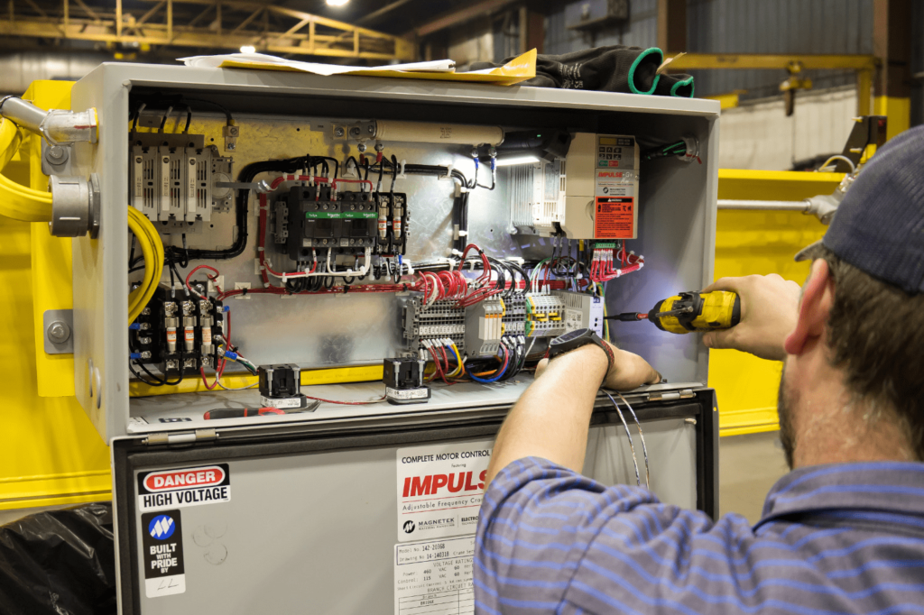
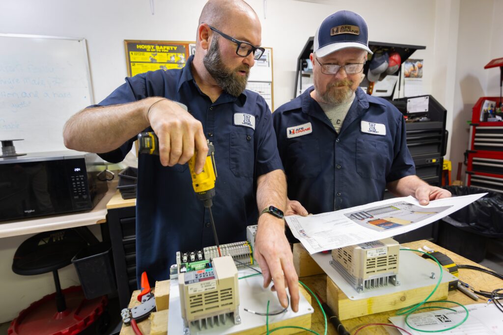
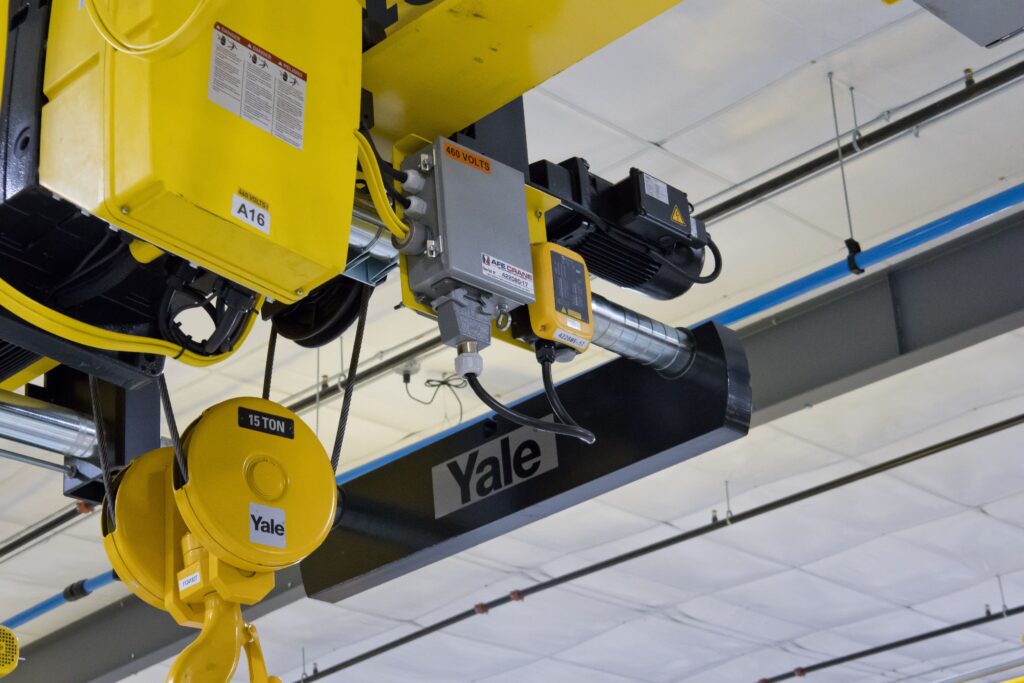
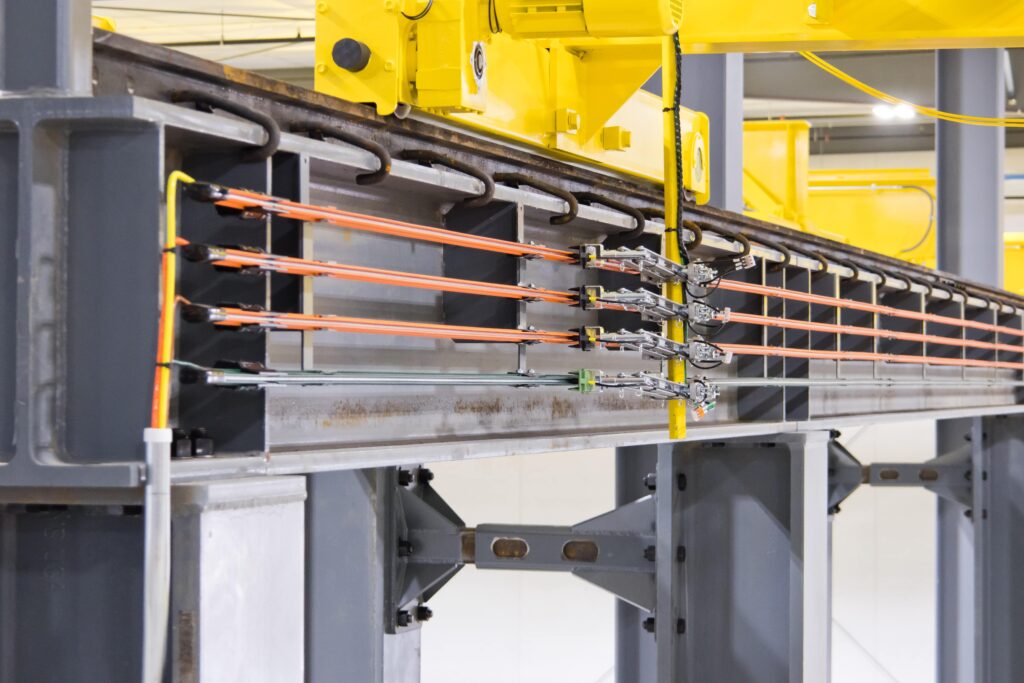
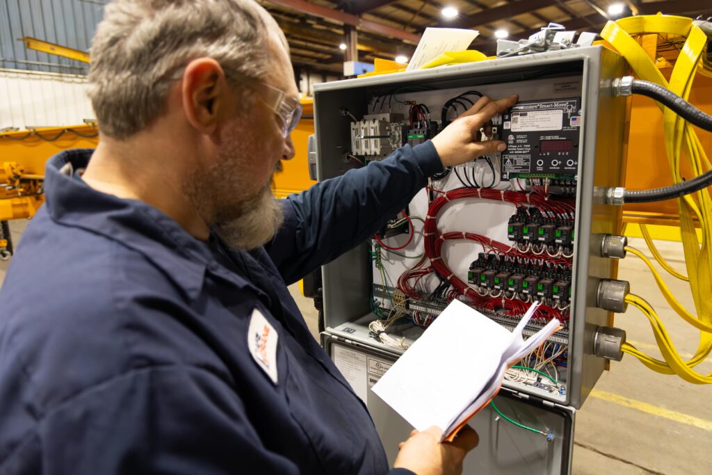
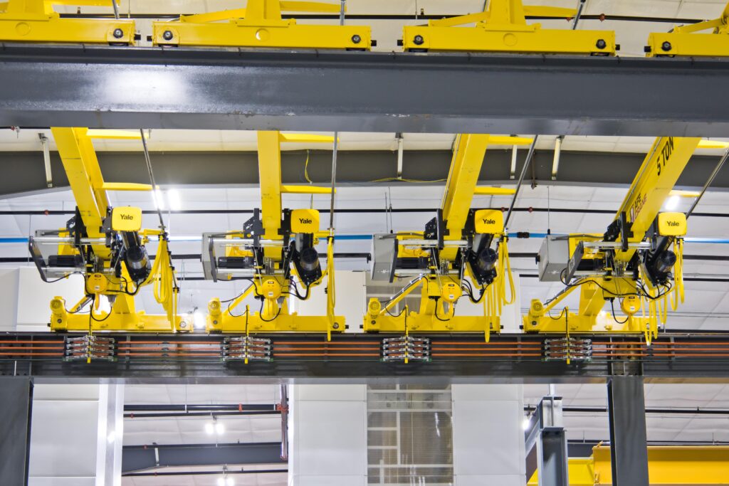
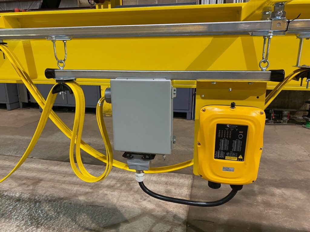
Standard System Controls

Contactor and Variable Frequency Drive (VFD)

Contactor controls are the most simple and economical way to control motors common to overhead bridge cranes.  A forward and reverse control signal is provided to reversing contactors allowing 3-phase power to be sent to the motor.  However, contactor controls can be hard to control because they only have two functions: on and off.

The better way to control drive and hoist motors is with a Variable Frequency Drive (VFD), also known as Adjustable Frequency Drives (AFD).  The primary advantage of VFD’s is the ability to program different parameters (or settings) into the device.  These parameters are able to change the minimum & maximum speed, acceleration time, and maximum allowable motor amperage just to list a few.

A VFD can also be set to Two Speed Infinitely Variable, where the operator can set the travel speed to anywhere within the min and max settings.   VFD’s can also be programed to slow down or stop motion if a particular sensor or device sends a input signal, eliminating relays for small control schemes.  Similar to contactors, VFD’s are supplied with two control signals and come in an array of sizes and versions.  Both contactors and VFD’s are sized by the Horsepower (or Full Load Amps) of the motor(s) it drives.

Radio and Pendant Controls

Cranes and other overhead lifting devices typically use a pendant for inputting hoist, trolley, crane and any other controls into the system.  Pendants are typically mounted directly under the hoist via pendant cord & strain relief, so the pendant is always by the hoist hook.  This is generally the most economical and best way to mount a pendant, unless one is lifting large, long, or unusual loads.  If this is the case, a walk-away pendant is the better option.  Walk-away pendants are mounted on a separate festoon track along the length of the bridge.  This allows the pendant (and crane operator) at one end of the crane and the hoist hook to be on the other keeping the operator a safe distance from the load.

Becoming more common in the overhead material handling industry are radio control systems.  Just like an RC car, a crane operator can stand anywhere (within range) and operate the crane wirelessly with a handheld transmitter.  This allows the operator to be completely safe by not standing under or close to the lifted load.  Many brands of radios also have additional features that can make lifting safer and easier in large assembly plants.  When using a radio a signal light, horn, or other warning device is required by ASME B30 standards.

System Power

Powering cranes are typically done in one of three ways: manual, electrical, or pneumatic.  Manually operated cranes are the most economical option due to the lack of electrical or pneumatic control systems required.  However, manually operated hoists, trolleys, and cranes use a chain fall that can clutter floor space and is very slow and timely to use.  These systems are typically best in small shops/garages where 2-3 lifts are being performed each week.

Electricity is by far the most common way to control cranes in small shops and garages but more so in large factories and assembly plants.  Typically, cranes are designed to use 3-phase power at 460 volts.  Other voltages can be used as well such as 575 and 230 volts, 120 or 240 single phase can also be used but are not as common.  The full amperage draw can vary depending on the size and number of motors and other controls being used but is typically 30 amps or less.

Supplying electricity to cranes are generally done by means of a conductor bar system.  Four runs of conductor bar are mounted to the length of the runway and four collector assemblies are mounted to the crane.  These collectors pick up the electricity off the conductor bars and feed the crane systems.  For areas that open power contacts and sparking is not permitted, rigid track festooning and flat cable is generally used.

Pneumatically controlled cranes are typically run using compressed air from the customer’s compressed air system.  Electric controls are often used instead of compressed air due to the large volumes of air that need to run a pneumatic hoist and crane.  A typical air hoist needs a system pressure of 90-125 psi.  Pneumatic cranes and hoists are typically used in special environments such as wash bays or hazardous locations where electrical items are not safe to use.  Cranes and hoist using compressed air typically use a taut-wire and self-retracting coiled hose.  For larger systems needing a large air supply, rigid track festooning w/ trolleys and flexible rubber airlines are used.

One & Two Speed Systems

Just about all motions of overhead lifting (hoist, trolley, and crane) can facilitate 1, 2 or more speeds.   The amount of speeds a hoist uses does not relate to its top lifting speed.  For example, if a trolley is specified to travel at 60 fpm, a 2-speed control system can operate that hoist at 15 fpm for 1st speed and 60 fpm for 2nd.  If a 3-speed system were used with the same hoist, 1st speed could be set at 15 fpm, 2nd at 45 fpm, and 3rd at the max of 60 fpm.  With the use of VFD’s and Infinitely Variable controls on the rise, 2-speed systems are typically the maximum used.  If a single speed system were used the trolley would only be able to travel at a rate of 60 fpm.  This may be fine with an empty hook, but when fully loaded, the load may be cumbersome or dangerous.  Many systems have 2-speed motion for all directions. This allows the user to make accurate movements.

A-B-Both Systems

In systems where there are multiple cranes/hoist being used simultaneously by one operator, an A-B-Both system may need to be implemented.  An A-B-Both system allows one operator to operate hoist A, or hoist B, or both hoist A & B.  A selector switch is normally on the radio transmitter or pendant for easy selection from the operator.  Using multiple hooking points and an A-B-Both control system is a safe means of lifting and moving items using multiple hoist.  It eliminates using both hands for controls and faulty communication between two operators.  A-B-Both controls can also be applied to separate cranes using the same runway.  More complex systems can be used when more components are utilized, for example Crane 1 with Hoists A & B, and Crane 2 with Hoists C & D.

Custom System Controls

Collision Avoidance System

Collision avoidance systems can keep cranes isolated without mechanical switches or devices.  These systems can be used to prevent impacts between cranes as well as other obstructions.  Reducing impacts can improve operator safety and reduce the wear and tear on equipment.  Collision avoidance systems can also be used to maintain a minimum distance between cranes to prevent overloading runways and support structure.  Keeping cranes segregated used to be done with bumpers, crane spacers, or limit switches.  A collision avoidance system typically consists of an optical sensor and a reflector.  The reflector is mounted on the crane or object that will be detected.  The sensor can be set for multiple distances.  This can allow you to use a slowdown and stop function at different distances.  Signal lights or alarms can be used to indicate when cranes or objects are being detected.  Programming the sensor is very easy.  It requires the push of one button when the crane is located at the desired distance from the crane or object.  Collison avoidance systems can be installed on new cranes and are easy to retrofit to existing crane systems.  The sensor can be integrated into cranes using a VFD or contactor controls.

Slowdown & Stop

 Adding slowdown & stop controls to a trolley or bridge adds many benefits to crane systems and employee safety.  Without this added feature, the only means of stopping a crane or trolley is with the use of end stops.  Depending on the size of crane and load being lifting, running into the end stops can put large and unnecessary impact forces on the trolley, crane, runway structure, and even the building.  By installing an additional set of sensors and changing a few parameters on the VFD, we can use this function.  Now, when the trolley is traveling towards the end stop a sensor will trip, which will then cause trolley to stop right before the end stop is met, eliminating most impact forces.  If one more sensor is added to the system, the slowdown function can be implemented.  This will allow the trolley to start slowing down at a given point to reduce load swing as much as possible.  In addition to reducing load swing and impact forces, the slowdown and stop feature can reduce bridge tread and wheel wear.  On a system without the above system, there is nothing stopping the wheels from spinning after the end stops are hit if the operator does not remove their finger from the button.  This can cause major damage to the spinning wheels and its running tread.  In some cases, wheel divots were formed so deep that the wheels would become trapped.  This costly and dangerous damage could be eliminated by adding a slowdown & stop control feature to a crane or trolley.

Automation & Other Controls

AFE Crane has the ability of making crane controls as simple as possible or as complex as need to keep employees safe and production running smoothly.  We can use a number electrical sensors including: photocells, limit switches, encoders, and laser scanners.  A number of other electrical components can be used, including: indicator lights, warning lights or buzzers, relays, programmable logic controllers (PLC’s), DC power supplies, and many more.  By using all of the above, AFE Crane can design and develop a system that fits your needs.  From creating zoned “no travel” areas, to special building column anti-collision controls for projecting cranes, and adding travel constrains so the hoist cannot lift unless other criteria have been met.

For more elaborate systems including large carriers transporting and queuing parts for a main assembly line, a more intricate control scheme can be used.  By using encoders, RFID tags, and scanners, each carrier can be mapped on a computer monitor or touch-pad display.  This allows one employee to keep track of any system errors or issues without the need to travel the entire plant.  Most of these systems are semi-automated, meaning that once a carrier is loaded the operator will push one button and the carrier will automatically travel to the next required station.  These systems can also be integrated with the customer’s shop management software to produce a seamless workflow.

Have A Question? Contact Us Today.

Click to submit an inquiry, or call us at (800) 728-0818.